12.1.5 VLAN、VTP、生成树配置
1.CISCO交换机配置
(1)配置二层端口
交换机所有端口默认的端口都是二层口,如果此端口已经配置成三层端口的话,则需要用switchport来使其成为二层端口。
可以配置快速以太口的速率为10/100Mbit/s及千兆以太口的速率为10/100/1000Mbit/s;但对于GBIC端口则不能配置速率及双工模式,有时可以配置nonegotiate,当需要连接不支持自适应的其他千兆端口时。
配置步骤如下。
①configure terminal进入配置状态。
②interface interface-type interface-id进入端口配置状态。
③speed{10|100|1000|auto|nonegotiate}设置端口速率。
④duplex{auto|full|half}设置全双工或半双工。
⑤end退出。
⑥show interfaces interface-type interface-id显示有关配置情况。
⑦copy running-config startup-config保存。
(2)配置三层端口
Catalyst交换机支持如下3种类型的三层端口。
·SVIs:即interface vlan。
注意:当生成一个interfaceVlan时,只有当把某一物理端口分配给它时才能被激活。
·三层以太网通道口(EtherChannel)。
·路由口:是指某一物理端口在端口配置状态下用no switchport命令生成的端口。
配置步骤如下。
①configure terminal进入配置状态。
②interface {interface-typeinterface-id}|{vlanvlan-id}|{port-channelport-channel-number}进入端口配置状态。
③no switchport把物理端口变成三层口。
④ip addressip_address subnet_mask配置IP地址和掩码。
⑤no shutdown激活端口。
⑥end退出。
(3)生成、修改以太网VLAN
1)全局模式下配置
①configure terminal进入配置状态。
②vlan vlan-id输入一个VLAN号,然后进入vlan配置状态,可以输入一个新的VLAN号或旧的来进行修改。
③name vlan-name输入一个VLAN名,如果没有配置VLAN名,默认的名字是VLAN号前面用0填满的4位数,如VLAN0004是VLAN4的默认名字。
④mtu mtu-size改变MTU大小。
⑤end退出。
⑥show vlan{name vlan-name|id vlan-id}验证。
⑦copy running-config startup config保存配置。
举例如下。
Switch#configure terminal
Switch(config)#vlan 20
Switch(config-vlan)#name test20
Switch(config-vlan)#end
2)VLAN数据库模式下配置
①vlan database进入VLAN配置状态。
②vlan vlan-id name vlan-name加入VLAN号及VLAN名。
③vlan vlan-id mtu mtu-size修改MTU大小。
④exit更新VLAN数据库并退出。
⑤show vlan{name vlan-name|id vlan-id}验证配置。
⑥copy running-config startup config保存配置。
举例如下。
Switch#vlan database
Switch(vlan)#vlan 20 name test20
Switch(vlan)#exit
3)删除VLAN
当删除一个处于VTP服务器的交换机上删除VLAN时,则此VLAN将在所有相同VTP的交换机上删除。当在透明模式下删除时,只在当前交换机上删除。
当删除一个VLAN时,原来属于此VLAN的端口将处于非激活的状态,直到将其分配给某一 VLAN。
①configure terminal进入配置状态。
②no vlan vlan-id删除某一 VLAN。
③end退出。
④show vlan brief验证。
⑤copy running-config startup config保存。
也可用vlan database进入VLAN配置状态,用no vlan vlan-id来删除。
4)将端口分配给一个VLAN
①configure terminal进入配置状态。
②interface interface-type interface-id进入要分配的端口。
③switchport mode access定义二层口。
④switchport access vlan vlan-id把端口分配给某一 VLAN。
⑤end退出。
⑥show running-config interface interface-id验证端口的VLAN号。
⑦show interfaces interface-id switchport验证端口的管理模式和VLAN情况。
⑧copy running-config startup-config保存配置。
使用default interface interface-id还原到默认配置状态。
举例如下。
Switch# configure terminal
Switch(config)# interface fastethernet0/1
Switch(config-if)# switchport mode access
Switch(config-if)# switchport access vlan 2
Switch(config-if)# end
5)配置VLAN Trunks
①configure terminal进入配置状态。
②interface interfae-type interface-id进入端口配置状态。
③switchport trunk encapsulation {isl | dot1q | negotiate}
配置trunk封装ISL或802.1Q或自动协商。
④switchport mode {dynamic {auto | desirable} | trunk}配置二层trunk模式。
⑤switchport access vlan vlan-id指定一个默认VLAN。如果此端口不再是trunk。
⑥switchport trunk native vlan vlan-id指定802.1QnativeVLAN号。
⑦end退出。
⑧show interfaces interface-type interface-id switchport显示有关switchport的配置。
⑨show interfaces interface-type interface-id trunk显示有关trunk的配置。
⑩copy running-config startup-config保存配置。
举例如下。
Switch# configure terminal
Switch(config)# interface fastethernet0/4
Switch(config-if)# switchport mode trunk
Switch(config-if)# switchport trunk encapsulation dot1q
Switch(config-if)# end
定义trunk允许的VLAN。默认情况下trunk允许所有的VLAN通过。可以使用switchport trunk allowed vlan remove vlan-list来去掉某一 VLAN。
①configure terminal进入配置状态。
②interface interface-type interface-id进入端口配置。
③switchport mode trunk配置二层口为trunk。
④sswitchport trunk allowed vlan {add | all | except | remove} vlan-list配置trunk允许的VLAN。
⑤end退出。
⑥show interfaces interface-type interface-id switchport验证VLAN配置情况。
⑦copy running-config startup-config保存配置。
举例如下。
Switch(config)# interface fastethernet0/1
Switch(config-if)# switchport trunk allowed vlan remove 2
Switch(config-if)# end
6)configure terminal 进入配置状态。
②vtp mode {server|client|transparent} 配置VTP模式。
③vtp domain domain-name 配置VTP域名。
④vtp password password 配置VTP密码。
⑤vtp pruning 配置VTP修剪。
⑥end 返回特权模式。
⑦show vtp state 查看VTP状态。
⑧copy running-config startup-config 保存配置。
举例如下。
Switch# configure terminal
Switch(config)#vtp mode server
Switch(config)#vtp domain csai
Switch(config)#vtp password csai2013
Switch(config)#end
Switch#show vtp state
Switch# copy running-config startup-config
7)使用STP实现负载均衡
负载均衡可以使用流量分流到其他平行的trunks上去。交换机为了避免环路,STP通常是阻断所有端口交换机之间只留一条链路。使用负载均衡后,可以把不同VLAN的流量分配到不同的trunk上。
可以通过配置STP端口权值和STP路径值来实现负载均衡。如果使用STP端口权值来配置,那么2条负载均衡的trunk必须连同一交换机上。使用路径值则即可以连相同的交换机及不同的交换机。
当同一台交换机的两个端口形成环路时,STP端口权值用来决定那个口是enable的,那个口是阻断的。可以通过配置端口权值来决定Trunk各走那些VLAN,有较高权值的端口(数字较小的)vlan,将处于转发状态,同一个VLAN在另一个Trunk有较低的权值(数字较大)则将处在阻断状态。即同一 VLAN只在一个Trunk上发送接收。
基于端口权值的负载均衡的网络拓扑如图12-16所示。
trunk1将发送和接收VLAN8-10的数据,trunk2将发送和接收VLAN3-6的数据。
配置如下。
(1)configure terminal 进入Switch 1配置状态。
(2)vtp domain csai配置VTP域。
(3)vtp mode server将Switch 1配置成VTP server。
(4)end退出。
(5)show vtp status 验证VTP的配置。
(6)show vlan验证VLAN。
(7)configure terminal 进入配置状态。
(8)interface fastethernet 0/1 进入F0/1端口。
(9)switchport trunk encapsulation dot1q 配置Trunk封装。
(10)switchport mode trunk 配置成Trunk。
(11)end退出。
(12)how interfaces fastethernet0/1 switchport验证VLAN配置。
(13)switch1上的F0/2上重复(7)~(11)步骤。
(14)在Switch 2的F0/1,F0/2上重复(7)~(11)步骤。
(15)show vlan在switch 2上验证已经学到相关的VLAN配置。
(16)configure terminal在Switch 1上进入配置状态
(17)interface fastethernet0/1进入要配置的端口。
(18)spanning-tree vlan 8 port-priority 10将端口权值10赋予VLAN 8。
(19)spanning-tree vlan 9 port-priority 10将端口权值10赋予VLAN 9。
(20)spanning-treevlan10port-priority10将端口权值10赋予VLAN 10。
(21)exit退回。
(22)interface fastethernet0/2进入F0/2。
(23)spanning-tree vlan 3 port-priority 10将端口权值10赋予VLAN 3。
(24)spanning-tree vlan 4 port-priority 10将端口权值10赋予VLAN 4。
(25)spanning-tree vlan 5 port-priority 10将端口权值10赋予VLAN 5。
(26)spanning-tree vlan 6 port-priority 10将端口权值10赋予VLAN 10。
(27)end退出。
(28)show running-config验证配置。
(29)copy running-config startup-config保存配置。
通过配置配置STP路径值也可以实现负载均衡,如图12-17所示。
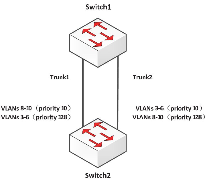
图12-16 基于端口权值负载均衡示意图
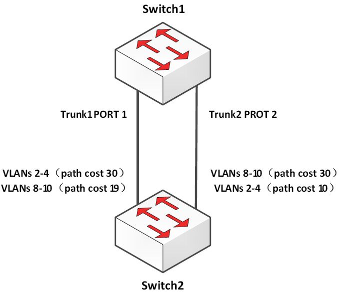
图12-17 基于路径值负载均衡示意图
Trunk1走VLAN8-10的流量,Trunk2走VLAN2-4的流量。
(1)configure terminal进入Switch 1配置状态。
(2)interface fastethernet 0/1进入F0/1。
(3)switchport trunk encapsulation dot1q配置封装。
(4)switchport mode trunk配置Trunk。
(5)exit退回。
(6)在F0/2口上重复(2)~(4)步骤。
(7)end退出。
(8)show running-config 验证配置。
(9)show vlan验证switch1已经学到VLAN。
(10)configure terminal进入配置状态。
(11)interface fastethernet 0/1进入F0/1。
(12)spanning-tree vlan 2 cost 30设置VLAN2生成树路径值为30。
(13)spanning-tree vlan 3 cost 30设置VLAN3生成树路径值为30。
(14)spanning-tree vlan 4 cost 30设置VLAN4生成树路径值为30。
(15)end退出。
(16)在switch1的F0/2上重复9-11步骤设置VLAN8、9、10生成树路径值为30。
(17)exit退出。
(18)show running-config验证配置。
(19)copy running-config startup-config保存配置。
2.HW交换机配置
(1)HW交换机命令视图
·用户视图(查看交换机的简单运行状态和统计信息):与交换机建立连接即进入。
·系统视图(配置系统参数)[Quidway]:在用户视图下键入system-view。
·以太网端口视图(配置以太网端口参数)[Quidway-Ethernet0/1]:在系统视图下键入interfaceethernet0/1。
·VLAN视图(配置VLAN参数)[Quidway-Vlan1]:在系统视图下键入vlan1。
·VLAN接口视图(配置VLAN和VLAN汇聚对应的IP接口参数)[Quidway-Vlaninterface1]:在系统视图下键入interface vlan-interface1。
·本地用户视图(配置本地用户参数)[Quidway-luser-user1]:在系统视图下键入local-useruser1。
·用户界面视图(配置用户界面参数)[Quidway-ui0]:在系统视图下键入user-interface。
(2)VLAN配置方法
1)配置方法
配置环境参数:SwitchA端口E0/1属于VLAN2,E0/2属于VLAN3。
组网需求:把交换机端口E0/1加入到VLAN2,E0/2加入到VLAN3。
VLAN配置流程如下。
①默认情况下所有端口都属于VLAN1,并且端口是access端口,一个access端口只能属于一个vlan。
②如果端口是access端口,则把端口加入到另外一个vlan的同时,系统自动把该端口从原来的vlan中删除掉。
③除了VLAN1,如果VLANXX不存在,在系统视图下键入VLANXX,则创建VLANXX并进入VLAN视图;如果VLANXX已经存在,则进入VLAN视图。
2)SwitchA相关配置
方法一:
①创建(进入)vlan2。
[SwitchA]vlan2
②将端口E0/1加入到vlan2。
[SwitchA-vlan2]port ethernet0/1
③创建(进入)vlan3。
[SwitchA-vlan2]vlan3
④将端口E0/2加入到vlan3。
[SwitchA-vlan3]port ethernet0/2
方法二:
①创建(进入)vlan2。
[SwitchA]vlan2
②进入端口E0/1视图。
[SwitchA]interface ethernet0/1
③指定端口E0/1属于vlan2。
[SwitchA-Ethernet1]port access lan2
④创建(进入)vlan3。
[SwitchA]vlan3
⑤进入端口E0/2视图。
[SwitchA]interface ethernet0/2
⑥指定端口E0/2属于vlan3。
[SwitchA-Ethernet2]port access vlan3
3)测试验证。
①使用命令disp cur可以看到端口E0/1属于vlan2,E0/2属于vlan3。
②使用display interface Ethernet0/1可以看到端口为access端口,PVID为2。
③使用display interface Ethernet0/2可以看到端口为access端口,PVID为3。
(3)端口的Trunk配置
1)配置环境参数
·SwitchA端口E0/1属于vlan10,E0/2属于vlan20,E0/3与SwitchB端口E0/3互连。
·SwitchB端口E0/1属于vlan10,E0/2属于vlan20,E0/3与SwitchA端口E0/3互连。
2)组网需求
·要求SwitchA的vlan10的PC与SwitchB的vlan10的PC互通。
·要求SwitchA的vlan20的PC与SwitchB的vlan20的PC互通。
3)SwitchA相关配置
①创建(进入)vlan10。
[SwitchA] vlan 10
②将E0/1加入vlan10。
[SwitchA-vlan10]port Ethernet 0/1
③创建(进入)vlan20。
[SwitchA]vlan 20
④ 将E0/2加入vlan20
[SwitchA-vlan20]port Ethernet 0/2
⑤实际当中一般将上行端口设置成trunk属性,允许vlan透传。
[SwitchA-Ethernet0/3]port link-type trunk
⑥允许所有的vlan从E0/3端口透传通过,也可以指定具体的vlan值。
[SwitchA-Ethernet0/3]port trunk permit vlan all
4)SwitchB相关配置
① 创建(进入)vlan10。
[SwitchB] vlan 10
② 将E0/1加入vlan10。
[SwitchB-vlan10]port Ethernet 0/1
③创建(进入)vlan20。
[SwitchB]vlan 20
④将E0/2加入vlan20。
[SwitchB-vlan20]port Ethernet 0/2
⑤实际当中一般将上行端口设置成trunk属性,允许vlan透传。
[SwitchB-Ethernet0/3]port link-type trunk
⑥允许所有的vlan从E0/3端口透传通过,也可以指定具体的vlan值。
[SwitchB-Ethernet0/3]port trunk permit vlan all
5)测试验证
①SwitchA vlan10内的PC可以与Switch Bvlan10内的PC互通。
②SwitchA vlan20内的PC可以与Switch Bvlan20内的PC互通。
③SwitchA vlan10内的PC不能与Switch Bvlan20内的PC互通。
④SwitchA vlan20内的PC不能与Switch Bvlan10内的PC互通。
(4)生成树STP配置
1)配置环境参数
①交换机SwitchA、SwitchB和SwitchC都通过GE接口互连。
②SwitchB和SwitchC交换机是核心交换机,要求主备。
2)组网需求
要求整个网络运行STP协议。
3)配置步骤
①SwitchA交换机配置。
启动生成树协议:[SwitchA]stp enable。
②SwitchB交换机配置。
启动生成树协议:[SwitchB]stp enable。
③配置本桥为根桥:[SwitchB]stp root primary。
④SwitchC交换机配置。
启动生成树协议:[SwitchC]stp enable。
配置本桥为备份根桥:[SwitchC]stp root secondary。
⑤SwitchD交换机配置。
启动生成树协议:[SwitchD]stpenable。
4)测试验证
①使用displaystp查看交换机STP运行状态。
②查看端口STP状态display stp interface EthernetXX是否正确。